Saturday, October 16, 2021

Acoustic-to-electric transduction by gas discharges

 This will be a stream-of-consciousness post on my favorite technology right now: the use of gas discharges to transduce acoustic waves into electronic signals. This type of transduction takes advantage of the fact that the electrical resistivity between two electrodes is directly proportional to the gas pressure. The pressure perturbation of an acoustic wave will therefore cause a minute fluctuation of the discharge current if the voltage between the electrodes is held fix. The transduced signal can be extracted simply by high-pass filtering the discharge current. Amplification of the signal is non-trivial. Several efforts have been made to use this transduction mechanism to make a viable "plasma microphone", including patents by Tri-Ergon's Vogt, Engl and Massolle (filed in 1921) and by Westinghouse's Thomas (filed in 1922). The Thomas device used a conventional atmospheric discharge and was used for experimental AM broadcasts but was never commercialized. The Vogt device ("Das Kathodophon") used a thermionic cathode and did see some commercial use in Germany from the late 1920s to late 1930s. There has also been academic research, for example by Fransson et al. in the early 1970s, and more recently by Bequin. The major obstacle to technological viability seems to be that atmospheric discharges are electrically noisy and produce noxious gases (ozone and nitrous oxides).

Instead of revisiting the hard problem of developing a plasma microphone to transduce sound propagating through air, back in 2016 I decided to try to tackle the simpler problem of using a gas-discharge tube to transduce acoustic waves propagating in solids and fluids. Instead of the multiple kV needed for atmospheric discharges, gas-discharge tubes can be operated with voltages as low as 80 V. Their discharges are also much less noisy and obviously noxious gases are not produced by noble gases (neon and argon) confined inside a sealed glass tube! This technology is now becoming mature enough to use and there are patents pending (I'm the inventor, the US patent is assigned to Princeton University). This post is a quick update on the technological development level.

I have been focusing on technical applications, especially the sensing of ultrasound in the frequency range of 60 kHz to 1 MHz. Spontaneous acoustic emissions at these frequencies can be produced when stress energy is released during early stages of metal fatigue. Detecting these acoustic emissions can therefore be used to predict catastrophic structural failure of metal structures (steel bridges, drilling platforms, etc.). Piezoelectric acoustic sensors are used for this application, but they have very limited service life under harsh operating conditions (including high ambient heat and neutron radiation). For the frequency range of interest here, I have found that commodity neon glow lamps make excellent transducers! Here are photos of an NE-2 type neon glow lamp powered off (to the left) and powered on (to the right) with a characteristic glow surrounding the cathode:


Here's is a comparison of the performance of a similar gas-discharge tube (same 1/4" diameter as the NE-2, but two thirds the length) with a commercial piezoelectric sensor:


As can be seen, the plasma sensor has a much flatter frequency response (that is, its sensitivity depends much less on frequency) resulting in better signal quality. At room temperature the plasma sensor is six times less sensitive at 100 kHz (the primary resonance of the piezo sensor), but six times more sensitive at 600 kHz. In the frequency range of interest, the plasma sensor sensitivity is within a 6dB range and most of that variation is probably due to the ultrasound transmitter used for the testing. Interestingly enough, for this test the plasma sensor performed better at 150 degrees Celsius than at room temperature with a factor of 2.5 increase of sensitivity. Here's is the same plot on a log scale:


This is pretty decent performance for a $0.12 gas-discharge tube versus a ~$100 commercial piezo sensor!

There are high-temperature piezo sensors available for temperatures up to 200 degrees Celsius (but using piezoelectric materials with reduced sensitivity). Here are the results of a high-temperature test with an NE-2 as the transducer:

As can be seen, after some transients as the tube heated up, the plasma sensor functioned normally (its sensitivity remained unchanged) for 100 hours at an ambient temperature of 400 degrees Celsius. In this case the sensitivity did thus not increase at higher temperature, as it did in the previous test. The transducer functioned normally after cooling off to room temperature, but a day later it was unable to form a discharge at the normal operating voltage. Our hypothesis is that air slowly leaked into the tube during cooling off. We are unaware of other ultrasonic acoustic sensors that function at these temperatures.

The plasma sensor should be able to withstand significant neutron irradiation, but we have yet to test this hypothesis. We expect the service life to be somewhat reduced as sputtering of cathode material is accelerated by neutron embrittlement.

In summary, the plasma ultrasonic acoustic sensor is now a viable alternative to conventional, piezoelectric sensors, especially in harsh operating conditions, or if low signal distortion is  a priority.

Friday, August 6, 2021

Rules for sub-GHz RF transmitters in the US

After a couple of years of absence from this sort of work, I need microcontrollers to communicate by RF for a couple of projects. I had a box full of cheap 315 and 433 MHz RF modules, as well as some 915 MHz LoRa ones, but decided to spend some time searching for alternatives in the 216 to 960 MHz frequency range. I jotted down some notes and subsequent thoughts that I’ll share in the form of this blog post.

Use of RF transmitters in the US is regulated by the Code of Federal Regulations Volume 47 (Telecommunication), Part 15 (Radio Frequency Devices), Subparts A (General) and C (Intentional Radiators). Transmitters “shall be certificated”, unless they are “home-built devices” as defined by paragraph 15.23. When I buy an RF module I assume, probably naively, that the seller provides me with a device from a manufacturer that has received the necessary certification for it. Do note that if you upgrade the antenna, or make any other modifications, you are responsible for any resulting violations of FCC rules.


For home-built devices, not built from a kit, you don’t need certification as long as you built five or less and they are for personal use only. You still need to make a reasonable effort to ensure they follow FCC rules. But it’d be possible to build some Proof-of-Concept devices that operate away from the usual frequencies, and still be in compliance.


I made a plot of the maximum field strength that is allowed for continuous (per paragraph 15.209) and periodic (15.231e) transmissions. Except for in the 915 MHz ISM band, continuous transmissions are severely limited to a field strength of not more than 200 μV/m, measured 3 m from the antenna. For a typical whip antenna (a monopole without a ground plane) that translates into a radiated power of less than -50 dBm, or 10 nW! That seems impractically low. In the 470-806 MHz UHF band, continuous transmission is not allowed. For intermittent transmissions, FCC will increase your power budget (but limits the bandwidth to 0.25% of the center frequency). Specifically 15.231e allows periodic transmissions of no more than one second duration, separated by a silent period of 10 seconds or 30 times the transmission duration, whichever is longer. The field strength limit is 1.5 mV/m at 216 MHz and ramps up to 5 mV/m at 470 MHz. For a 315 MHz transmitter, periodic operation is then allowed at -30 dBm and at 433 MHz at -25 dBm. When manually operated as a remote control, and for other even more specialized applications, higher transmitter power is allowed. Paragraph 15.205 defines four restricted bands where no unlicensed transmissions are allowed. In the ISM band from 902-928 MHz both continuous and periodic transmissions can have a field strength of 50 mV/m (corresponding to an output power of about 0.5 mW).


I also plotted the frequency ranges populated by TV broadcasts and 5G, as well as dotted lines to mark the 315, 433, 868 and 915 MHz frequencies for which RF modules are widely available. So why the ubiquity of these frequencies? Well, 915 MHz is easy, since it’s an ISM band and allows much higher transmission power. Similarly, 433 MHz is an ISM band in Europe and Africa but there is nothing particular about it in the US. I’m guessing the day job of 315 MHz transmitters is as remotes for garage-door openers. From my perspective, the 868 MHz ones are the least common ones (I didn’t find a single one in my box of RF modules). I think it’s used for LoRa in Europe so it probably has some special status there. In the US it’s inside the 5G n26 band downlink!


Garage-door openers commonly used frequencies anywhere in the 300 to 400 MHz range until the mid 1990s. I have a couple of retired ones from “Whistler Auto-Mation Products” with adjustable frequencies. 390 MHz then seems to have become the canonical frequency. In 2004 DOD deployed new Land Mobile Radios that operate in the range 380 to 399.9 MHz and garage doors close to military bases promptly stopped working! After this debacle, 315 MHz seems to be the frequency of choice. This is an interesting lesson on the use of unlicensed (“Part 15”) devices, they should be able to handle interference from authorized spectrum users.


No dramatic changes in the last four to five years, as expected. The higher UHF TV channels have all been taken over by 5G. UHF TV used to go up to channel 83 (890 MHz), but now stops at channel 36 (608 MHz). The 868 MHz RF modules seem like a bad idea in the US, since they can interfere with cell phone signals. “Channel 13.5”, the frequency range of 216 to 470 MHz (so nicknamed because it’s between the VHF 13 and UHF 14 TV channels) seems to be the sweet spot for lightweight radio communication over tens of meters. I’ll probably end up comparing 315 and 433 MHz and use the one with least local noise and interference.

Wednesday, April 4, 2018

LoRaWAN in central New Jersey in early 2018?

I bought a couple of LoRa RF modules, including a 915 MHz Hope RF RFM95, last fall. The plan was to hook it up to an Arduino and use IBM's LMIC library to make a simple LoRa transceiver, get a developer account with a LoRaWAN service provider and start experimenting.

However, there was a snag. Senet does offer developer accounts, but doesn't currently have coverage in my neck of the woods, in central New Jersey, about halfway between Philadelphia and New York City. Comcast offers LoRa service, but calls it "machineQ", and also doesn't currently have coverage at my location. I didn't find any information about Comcast LoRa developer accounts. In fact it sounds like it's mandatory to use the Murata mQModule with the Comcast mQSpark dev kit to connect to the Comcast LoRaWAN, not very developer friendly.

So not only is there currently no coverage by commercial LoRaWAN service providers, they might not let you connect with your uncertified $5 RFM95 transceiver. The cheapest certified LoRa RF module I can find is the $15 RN2483, not only a bit pricey for use with an IoT sensor, but might still not let you connect with machineQ.

recent blog post by Omkar Joglekar documents how he built a LoRa transceiver very similar to what I had in mind, but much more ambitious with nice weatherproofing and a fancy monopole antenna with ground radials. He was able to get credentials to connect to the Tata Communications LoRaWAN. Clearly Tata Communications knows how to get early buy in from developers!

My current Plan B is to join The Things Network (TTN) by setting up my own LoRa gateway, since the nearest gateways on their coverage map are about 20 miles away, way too far even for LoRa. I have a single-channel LoRa gateway on the way on the slow boat from Shenzhen.

Wednesday, March 21, 2018

Bug zapper power supply

I have a $4 bug zapper that uses two AA batteries for a voltage source. I've measured the output voltage before to about 1.4kV and today I decided to measure the power supply operating frequency and ripple amplitude. Here's the bug zapper with an improvised high-pass filter and my trusty pocket scope standing by:

Hey, this actually works! Notice the hands-free high-tech solution for keeping the bug zapper on while I fiddled with scope settings:

And a close up of the scope:

So the operating frequency is a disappointingly low 18.8kHz, but the ripple amplitude is an impressively low ±30mV riding on 1.4kV DC. A modified bug-zapper booster design for neon glow lamps definitely seem worth revisiting down the road, but for now I'll stick to refining the voltage-multiplier version.

Voltage-multiplier boost converter for neon glow lamp

And now back to the regularly scheduled programming! I had second thoughts about pursuing the inductor-based boost converter design to power a neon glow lamp with a standard 9V battery. Non-ideal effects are significant for both the inductor and the transistor switch and it wasn't obvious that I'd be able to get the booster to operate above a megahertz. I might return to this design later and hope to ultimately replace the inductor with a flyback transformer, but for now I'm going with a more straightforward voltage-multiplier boost converter.

For the first iteration, the square-wave oscillator is unchanged except that it's input voltage is doubled to 18V by using two 9V batteries in series. I wasn't sure how many stages the voltage multiplier would need, but with 18V input I got away with using a 4-stage Greinacher (a.k.a. Cockcroft-Walton) multiplier. Here it is on two mini breadboards (voltage multiplier to the left and NE555 square-wave oscillator in the back to the right:

The components were what I had available. The diodes were bargain "germanium" diodes I bought a couple of years ago. I'm pretty sure they're just generic silicon signal diodes, but they seem to work well enough for this application. The voltage rating of the caps was a bit marginal and I used the lowest capacitance values a SPICE simulation told me I could get away with without reducing the output voltage. I did this over two months ago and I don't remember the oscillator frequency, but it must have been less than 200kHz. Anyway, this first crude attempt was encouraging enough. Here's a cheap multimeter showing an output voltage of 80.8V, more than enough to light a neon glow lamp:


Saturday, February 3, 2018

Humerus Varnhemiensis

recent imgur re-post  of a not-so-recent facebook post by Historiska, the Swedish national historical museum, has created a lot of attention for Humerus Varnhemiensis, the Varnhem humerus, a medieval bone repaired by a copper-sheet cylinder. The machine translation of the original FB post from Swedish to English is lacking, and a friend asked me for my translation. This piqued  my interest and since it seems that the authoritative scientific paper on Humerus Varnhemiensis is not as widely read as it deserves to be, I'll make this post with a link to it, a summary, and some of my own idle speculation.
Picture of Varnhem humerus (from Swedish Wikipedia page on Varnhem)

Varnhem is now a small, and shrinking, town in the middle of nowhere in south-central Sweden. The Varnhem Cistercian monastery is historically prominent as a center of early Swedish Christianity, with Christian graves dating back to the 800s, and as the burial place of Swedish regent Birger Magnusson, who founded the new capital of Stockholm in 1252. The Varnhem humerus was found in the cloister aisle in 1928. It probably dates to between 1260 and 1527 and is remarkable because it shows signs of healing after being repaired with a copper-sheet cylinder. It is a unique example of seemingly anachronistic, successful, advanced surgery from the Middle Ages. My initial reaction when I heard about it was very skeptical, but Hallbäck's scholarly work on the topic seems convincing to me, as a layman in this area.

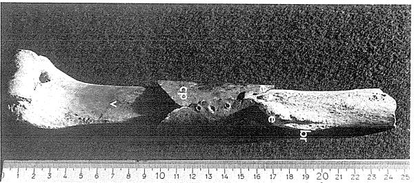
With the usual search engines, I could not find Hallbäck's paper, published in the journal "Ossa: international journal of skeletal research". However, using LIBRIS, the catalog search engine for all Swedish libraries, I found a PDF with a scan of the relevant issue. I extracted a 1.1 MB PDF with the paper of interest: Hallbäck, D.-A. (1976/7). A Medieval (?) bone with a copper plate support, indicating an open surgical treatment. Ossa 3/4, 63–82. It's a 20-page paper, written in English, and well worth a read in its entirety. There are 12 figures, 4 of them X-ray images, providing very compelling evidence.

In summary Hallbäck finds that the humerus is probably from the late medieval time period, 1260-1527, and less probably from 1150-1260. There is also a slight chance that the bone is as recent as from 1674-1695 (hence the awkward question mark in the title of the paper), when the church was used for burials of nobility, but its location in the monastery, not the church, contradicts that. Carbon-14 dating could not be used without unacceptable damage to the bone. The bone is wrapped in a "remarkably pure copper" cylinder, 7.3 cm long, and and about 0.7 mm thick. The cylinder has three pairs of holes, where it would have been held together by rivets, or similar, now gone. When the holes are lined up, the cylinder snugly fits around the bone. The paper refers to the cylinder material as copper plate, but if I went to Home Depot to buy some, I'd ask for copper sheet. A plate would be thicker and not possible to bend with your bare hands. The bone has a healed fracture ("proliferative bone reaction"), a porous area indicative of infection, and two "exostoses", bone growths on the surface of the bone, the larger of which has begun to cover the copper sheet! There is thus overwhelming evidence that the patient survived the surgery and recovered.
Figure 5 from the paper. The copper sheet is marked "cp", the proliferative bone reaction "br" and the exostoses "e".

The paper concludes: "My assumption is that the injury was caused by a cut from, for instance an axe or a sword, which led to an open wound, with the bared bone visible. The bone was probably not cut in two pieces. The plate was placed round the bone to bring about stabilization. At the same time, the pure copper had an antibacterial effect on the wound. Whether this effect was deliberate or not is impossible to say. Judging from the bone, and considering the well developed exostoses and the proliferative bone reaction, as well as the lack of fracture notches on the X-ray pictures, the patient must have survived for years, may be decades. Note that nothing can be said about the function of the arm after the operation".

My speculation is that the patient was a warrior and local nobleman with rare access to state-of-the-art medical care provided by Cistercian monks at the Varnhem monastery. His left arm was nearly severed in combat when an axe splintered his shield, peeled the flesh off the bone on the outside of the upper arm and fractured the bone. By the time he reached Varnhem the wound was infected and his physician decided to kill two birds with one stone and use a copper sheet wrapped around the already partially exposed bone to both stabilize the fracture and fight the infection. The recovery of the patient is impressive, but I find the skill of the physician even more impressive. Quoting Hallbäck: "The fixation of the plate so closely to the bone as in this case entails seriously damaged soft parts, and it is a true surgical exploit to carry through this operation so that the patient survived". Where did this Cistercian monk learn to perform medicine at this level? Was this kind of medical knowledge widespread within his order? Did he attend medical school at one of the handful of universities that existed at the time in continental Europe (Sweden's first university, in Uppsala, did not open until 1477)?

Friday, December 1, 2017

Neon glow lamp centennial

On November 30, 1917, Pennsylvanian Daniel McFarlan Moore, while working for General Electric in New Jersey, filed the patent for the neon glow lamp. Here's the top of the patent filing:
The top of the first page of Moore's patent filing for the neon glow lamp (US Patent 1,316,967)
D-mac called his invention a "gaseous-conduction lamp". In my opinion an apter name would have been "negative-glow lamp". At the time, it was commonly referred to as a "Moore lamp" and today we mostly call it "neon glow lamp".
Early gas-discharge tubes of the Geissler type existed at the time. In a Geissler tube most of the light is emitted by the positive-column part of the discharge. The negative-glow region close to the cathode only occupies a small fraction of the length of the tube. Modern fluorescent lamps, including CFLs, and the gas-discharge tubes used in neon signs are direct descendants of the Geissler tube. Moore's invention was to tweak the gas pressure and electrode spacing to make the negative glow occupy most of the discharge. In plasma physics we call this a short, or restricted, glow discharge and some weirdos with too much time on their hands perform elaborate computer simulations of such lowly devices.
The value of Moore's invention is that a short glow discharge can be operated at much lower voltages. Moore used an 80-20 mixture of neon and helium and mentions in the patent that 220 volts is then sufficient to turn the lamp on. In the US at that time, 220 volts was a common line voltage for commercial lighting, so that was probably his target voltage. Moore also made his lamp mechanically compatible with incandescent light bulbs:
One version of Moore's lamp, compatible with an incandescent bulb. The electrodes (13 and 14) are mounted on glass rods attached to the base of the glass tube. Figure from the patent filing.

With an optimal Penning mixture (99-1 neon-argon mixture), mains voltages of 110 volts, or even 100 volts, are more than sufficient. Miniature neon glow lamps are a commodity and can be bought for 6 cents to 60 cents, depending on order size and if you have time to wait for the boat from Shenzhen. They can be operated at DC or AC (as discussed at length in the patent filing) at voltages from about 75 volts, to all common mains voltages globally, up to the point where the glow discharge transitions to an arc discharge and the inside of the tube becomes covered by cathode material, causing a short circuit.
So, well done, Daniel McFarlan Moore! A wonderful invention, with some properties that could enable some novel applications, but that's another post, or two...